
Views: 45
Durability benefits of PTFE coated fiberglass
- Lifespan exceeding 30 years
- Can withstand temperatures of -100 F to +450 F (-73 C to +232 C)
- Tensile strength of 500,000 PSI (more than 10 times the tensile strength of steel)
- Chemically inert
- Weather-resistant
- Resistant to micro-organisms
- Moisture-resistant
- Immune to UV degradation
- Resists the build-up of environmental pollution
- Does not discolor over time
- Does not become brittle over time
Environmental benefits of PTFE coated fiberglass
- Energy Star rated
- Cool Roof Rating Council certified
- PTFE coated fiberglass membranes reflect up to 73% of solar heat and hold only 7% on their exterior surface
- PTFE coated fiberglass provides thermal insulation to a degree similar to conventional glazing
- U value of approximately 4.0-5.0 for a single-layer application
- High shading coefficient, resulting in energy savings over traditional glass glazing
Lighting benefits of PTFE coated fiberglass
- Highly transparent
- It allows natural daylight to reach the people below while also providing shading
- It is translucent, but still screens out ultraviolet rays and excess heat
- Reflects 75% of sunlight
- Absorbs 10% of sunlight
- Transmits 15% of sunlight
Maintenance benefits of PTFE coated fiberglass
- Regularly self-cleaning with rainwater
- A manual clean every 2-5 years is recommended, but because the fabric strength can support human weight, this can be done easily with jet-washers or soft brushes and access to the roof
- No internal cleaning required
- PTFE coated fiberglass installs in a buff color and bleaches to a bright white with sun exposure, so the structure self-maintains a bright white appearance over time
Safety benefits of PTFE coated fiberglass
- US Fire-Rated Noncombustible ASTM E-136, Class A Smoke ASTM E-84, Burning Brand E-108, CSFM Title 19, Pass NFPA 701
- Inherently non-flammable
- Class 1 rating in surface spread of flame testing
- UK Class 0 performance in BS476 pt6 fire propagation tests
Design benefits of PTFE coated fiberglass
- Flexible
- Lightweight (approximately 0.3 pounds per square foot, or 1.5kg per square meter)
- Single panels can be fabricated in almost any size and shape
- Large spans can be reinforced with structural cables
- PTFE coated fiberglass has highly elastic properties (10.5 x 10⁶ PSI modular elasticity)
- It does not significantly expand or shrink under stress
- It provides a significant degree of noise absorption and sound attenuation
- PTFE coated fiberglass can support up to 1,000 pounds per square inch (18 kg per mm)
- It can become a stage for beautiful and dramatic lighting effects
Views: 205
Tarpaulin tearing strength by the trouser tear method
1. Scope
This standard specifies a method of determining the tarpaulin tearing strength under specified conditions. It is applicable to products that, because of their flexibility, do not tear when clamped between the grips of a tensile testing machine. The method makes it possible to compare samples of different products provided their thickness does not differ by more than 10%.
2. Normative references
This standard incorporates, by dated or undated reference, provisions from other publications. These normative references are cited at the appropriate places in the text, and the titles of the publications are listed below. For dated references, subsequent amendments to or revisions of any of these publications apply to this standard only when incorporated in it by amendment or revision. For undated references, the latest edition of the publication referred to applies.
| DIN 51220 | General requirements for materials testing machines, including verification and calibra- tion |
| DIN 53370
DIN 53515 |
Determining plastic film and sheeting thickness by the stylus method
Determination of tear strength of rubber and plastic film by Graves angle testing with cuts |
| DIN EN ISO 291
DIN EN ISO 527-1 |
Plastics – Standard atmospheres for conditioning and testing (ISO 291 : 1997)
Plastics – Determination of tensile properties – Part 1: General principles (ISO 527-1 : 1993 + Corr 1 : 1994) |
| DIN EN ISO 7500-1 | Metallic materials – Verification of static uniaxial testing machines – Part 1: Tension/com- pression testing machines – Verification and calibration of the force-measuring system (ISO 7500-1 : 1999) |
3. Concept
Tear resistance
Ratio of the force with which a trapezoidal trouser-shaped specimen as shown in figure 1 resists tear, to the specimen thickness.
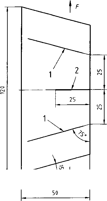 Figure 1: Template
Key
- Grip clamping marks
- Incision
4. Specimens
4.1 Sampling and specimen preparation
Specimens as shown in figure 1 shall be cut from the product to be tested. If possible, they shall be taken pap allel and transverse to the manufacturing direction (machine direction) of the film or sheeting so as to permit determination of the tear resistance in both directions as defined by the direction of the incision.
NOTE: If only one piece of the product is available and its manufacturing direction cannot be determined, specimens are to be taken in two directions normal to each other.
The cut directions shall be marked.
The use of a template as shown in figure 2, made of a cut-resistant material, will make it easier to cut out the specimen and make the incision with a knife or razor blade, and to make the grip clamping marks using a pen cil, ballpoint pen or grease pencil.
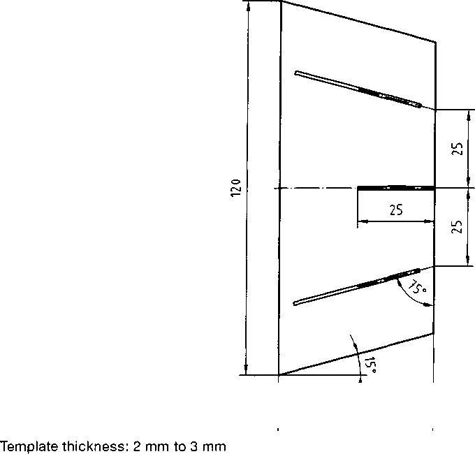
Figure 2: Template
4.2 Number of specimens
A minimum of five specimens shall be tested. If specimens are to tested in both directions, at least five shall be taken for each direction. In arbitration cases, at least ten specimens in each direction are to be tested.
5. Apparatus
5.1 Tensile testing machine
Class 1, as in DIN EN ISO 7500-1, conforming to the requirements of DIN 51220 and fitted with a device for gripping the specimen at the marks (see figure 1).
5.2 Measuring device
For measuring the specimen thickness as in DIN 53370.
6. Procedure
Carry out the tear test in a 23/50 standard atmosphere as in DIN EN ISO 291.
NOTE: In many cases, additional tests performed at lower and higher temperatures are recommended. For this purpose, an environmental test chamber shall be used during testing, capable of maintaining the required temperature to within 0.5 °C